Home
/ Cmos Inverter 3D / Monolithic 3d Cmos Using Layered Semiconductors Sachid 2016 Advanced Materials Wiley Online Library / Friends ఈ video లో నేను cmos inverter gate layout diagram or cmos not gate layout diagram ని microwind software use.
Cmos Inverter 3D / Monolithic 3d Cmos Using Layered Semiconductors Sachid 2016 Advanced Materials Wiley Online Library / Friends ఈ video లో నేను cmos inverter gate layout diagram or cmos not gate layout diagram ని microwind software use.
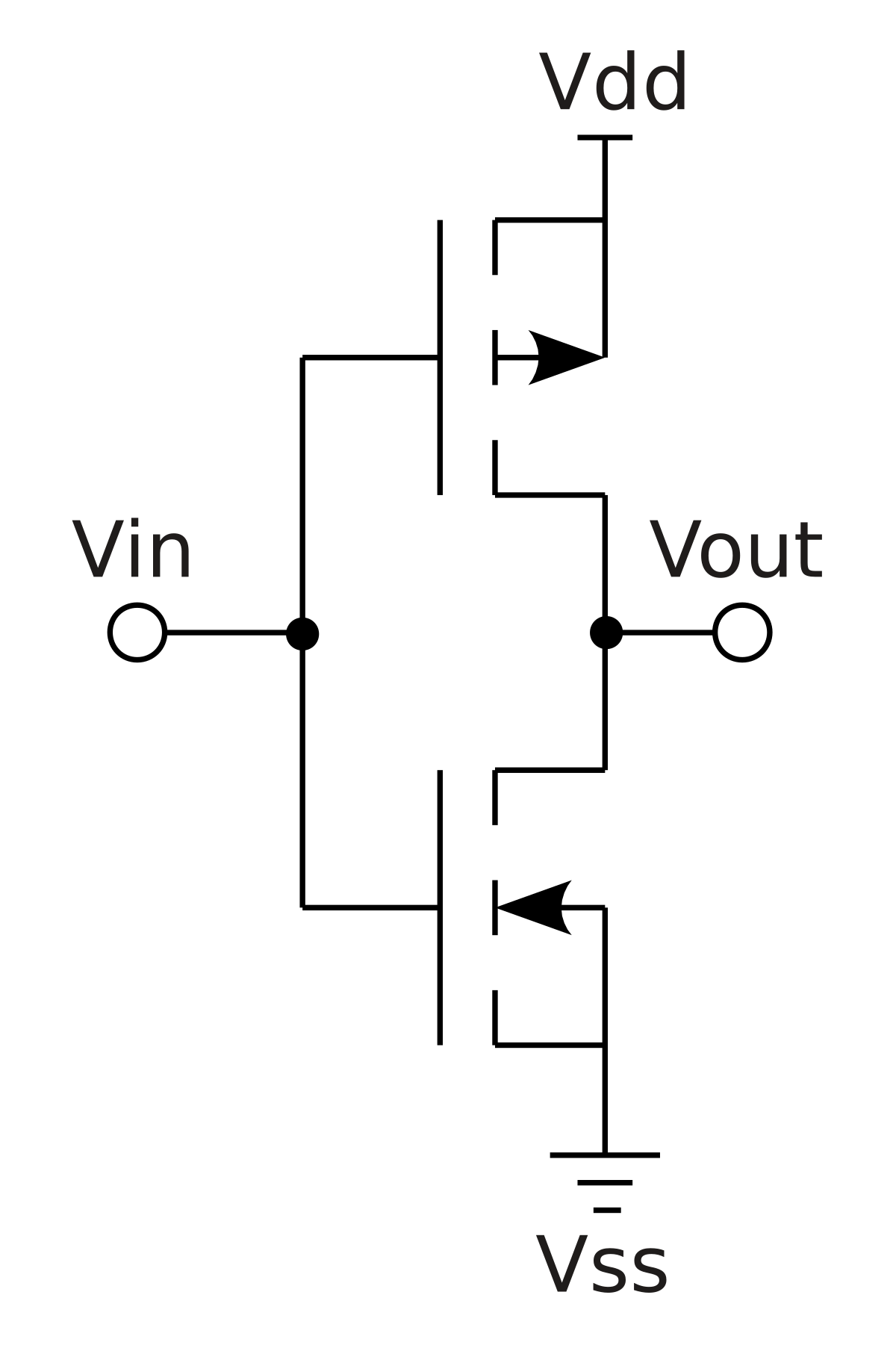
Cmos Inverter 3D / Monolithic 3d Cmos Using Layered Semiconductors Sachid 2016 Advanced Materials Wiley Online Library / Friends ఈ video లో నేను cmos inverter gate layout diagram or cmos not gate layout diagram ని microwind software use.. Make sure that you have equal rise and fall times. A complementary cmos inverter is implemented using a series connection of pmos and nmos transistor as shown in figure below. As you can see from figure 1, a cmos circuit is composed of two mosfets. The cmos inverter the cmos inverter includes 2 transistors. The cmos inverter collections found on the site are equipped with all the fascinating features such as intelligent cooling technology for faster and smart browse through the varied cmos inverter ranges at alibaba.com and buy the best of these products.
Cmos inverter fabrication is discussed in detail. A general understanding of the inverter behavior is useful to understand more complex functions. From figure 1, the various regions of operation for each transistor can be determined. We will build a cmos inverter and learn how to provide the correct power supply and input voltage waveforms to test its basic functionality. It consumes low power and can be operated at high voltages, resulting in improved noise immunity.
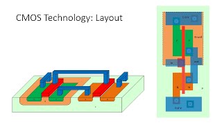
Cmos Tech Nmos And Pmos Transistors In Cmos Inverter 3 D View Youtube from i.ytimg.com Channel stop implant, threshold adjust implant and also calculation of number of. • design a static cmos inverter with 0.4pf load capacitance. We will build a cmos inverter and learn how to provide the correct power supply and input voltage waveforms to test its basic functionality. Cmos inverter fabrication is discussed in detail. In order to plot the dc transfer. Make sure that you have equal rise and fall times. Yes, cmos does dissipate static power. Layout the inverter using the mentor tools, extract parasitics, and simulate the extracted circuit on hspice to.
These products are all ce, iso, rohs certified.
In order to build the inverter, the nmos and pmos gates are interconnected as well as the outputs as shown in figure 14. Complementary metal oxide semiconductors (cmos). Posted tuesday, april 19, 2011. The cmos inverter collections found on the site are equipped with all the fascinating features such as intelligent cooling technology for faster and smart browse through the varied cmos inverter ranges at alibaba.com and buy the best of these products. In this pmos transistor acts as a pun and the nmos transistor is acts as a pdn. More experience with the elvis ii, labview and the oscilloscope. The most basic element in any digital ic family is the digital inverter. This may shorten the global interconnects of a. Experiment with overlocking and underclocking a cmos circuit. These characteristics are similar to ideal amplifier characteristics and, hence, a cmos buffer or inverter can be used in an oscillator circuit in conjunction with other passive components. This note describes several square wave oscillators that can be built using cmos logic elements. Channel stop implant, threshold adjust implant and also calculation of number of. Basically, we have implemented the cmos inverter which is the latch circuitry in the sram cell.
Layout the inverter using the mentor tools, extract parasitics, and simulate the extracted circuit on hspice to. Cmos inverter fabrication is discussed in detail. Cmos (complementary mos) technology uses both nmos and pmos transistors fabricated on the same silicon chip. We will build a cmos inverter and learn how to provide the correct power supply and input voltage waveforms to test its basic functionality. Experiment with overlocking and underclocking a cmos circuit.
Http Nano Eecs Berkeley Edu Publications Apl 2017 3d 20cmos 20inverter Pdf from You might be wondering what happens in the middle, transition area of the. Switching characteristics and interconnect effects. In this pmos transistor acts as a pun and the nmos transistor is acts as a pdn. Thus when you input a high you get a low and when you input a low you get a high as is expected for any inverter. As you can see from figure 1, a cmos circuit is composed of two mosfets. The cmos inverter the cmos inverter includes 2 transistors. Cmos inverter fabrication is discussed in detail. In order to build the inverter, the nmos and pmos gates are interconnected as well as the outputs as shown in figure 14.
Note that the output of this gate never floats as is the case with the simplest ttl circuit:
Experiment with overlocking and underclocking a cmos circuit. Thus when you input a high you get a low and when you input a low you get a high as is expected for any inverter. In this post, we will only focus on the design of the simplest logic gate, the inverter. we will try to understand the working of the cmos inverter. Even if you ask specifically cmos inverter, i will write a more broad answer. The pmos transistor is connected between the. This may shorten the global interconnects of a. Voltage transfer characteristics of cmos inverter : • design a static cmos inverter with 0.4pf load capacitance. Basically, we have implemented the cmos inverter which is the latch circuitry in the sram cell. First of all, static power is defined as the so, it is the width, mathw/math, which is increased at will to increase the peak current of the mos transistors, and that increase in current will. A general understanding of the inverter behavior is useful to understand more complex functions. These circuits offer the following advantages Noise reliability performance power consumption.
Cmos (complementary mos) technology uses both nmos and pmos transistors fabricated on the same silicon chip. This note describes several square wave oscillators that can be built using cmos logic elements. The device symbols are reported below. In order to plot the dc transfer. The most basic element in any digital ic family is the digital inverter.
Cmos Wikipedia from upload.wikimedia.org Now, cmos oscillator circuits are. The most basic element in any digital ic family is the digital inverter. The device symbols are reported below. Note that the output of this gate never floats as is the case with the simplest ttl circuit: It consumes low power and can be operated at high voltages, resulting in improved noise immunity. • design a static cmos inverter with 0.4pf load capacitance. Complementary metal oxide semiconductors (cmos). Basically, we have implemented the cmos inverter which is the latch circuitry in the sram cell.
Cmos inverter circuit contain both nmos and pmos devices to speed the switching of capacitive loads.
More experience with the elvis ii, labview and the oscilloscope. Voltage transfer characteristics of cmos inverter : Note that the output of this gate never floats as is the case with the simplest ttl circuit: Make sure that you have equal rise and fall times. Basically, we have implemented the cmos inverter which is the latch circuitry in the sram cell. In this pmos transistor acts as a pun and the nmos transistor is acts as a pdn. Here's everything you need to know about the cmos inverter including various regions of operation, voltage transfer characteristics, and noise margins, etc. It consumes low power and can be operated at high voltages, resulting in improved noise immunity. The cmos inverter the cmos inverter includes 2 transistors. Complementary metal oxide semiconductors (cmos). First of all, static power is defined as the so, it is the width, mathw/math, which is increased at will to increase the peak current of the mos transistors, and that increase in current will. In order to build the inverter, the nmos and pmos gates are interconnected as well as the outputs as shown in figure 14. These characteristics are similar to ideal amplifier characteristics and, hence, a cmos buffer or inverter can be used in an oscillator circuit in conjunction with other passive components.